


ESP8266 모듈중
ESP-12F 사용하여
OLED LCD + SD 카드 + 타이머?
OLED = I2C로 작동
SD 카드 = SPI 모드로 작동
작성한 코드
// ============================================================================================
// ESP8266 보드 설치하기
// https://learn.sparkfun.com/tutorials/esp8266-thing-hookup-guide/installing-the-esp8266-arduino-addon
// To begin, we’ll need to update the board manager with a custom URL. Open up Arduino,
// then go to the Preferences (File > Preferences). Then, towards the bottom of the window,
// copy this URL into the “Additional Board Manager URLs” text box:
//  ==> http://arduino.esp8266.com/stable/package_esp8266com_index.json
// Hit OK. Then navigate to the Board Manager by going to Tools > Boards > Boards Manager.
// There should be a couple new entries in addition to the standard Arduino boards.
// Look for esp8266. Click on that entry, then select Install.
// SSD1306 Lib for ESP8266
// https://randomnerdtutorials.com/esp8266-0-96-inch-oled-display-with-arduino-ide/
// https://github.com/squix78/esp8266-oled-ssd1306/archive/master.zip
// unzip to : C:\Users\*********\Documents\Arduino\libraries
// other lib not tested
// https://github.com/ThingPulse/esp8266-oled-ssd1306
//
// Note : esp8266 board generic unknown error
// https://arduino-esp8266.readthedocs.io/en/latest/faq/a04-board-generic-is-unknown.html#how-to-fix-it
// 아래 폴더 아래에 있는 오래된 것 삭제 후 재시작
// => C:\Users\**********\AppData\Local\Arduino15\packages\esp8266\hardware
//  The blue LED on the ESP-01 - GPIO1 : BLUE = TxD --> GPIO 1, RxD = GPIO 3
//  The blue LED on the Wemos D1 mini ESP-12F - GPIO2
//  10-bit analog ADC. The ADC range is from 0V to 1.0V (0 ... 1023)
// Timer & Ticker Exam :
//   https://circuits4you.com/2018/01/02/esp8266-timer-ticker-example/
//   'timer 0' is for WiFi, only 'timer 1' can be used
//   However 'Ticker' is prefered due to 'crash'
// SD : https://www.instructables.com/id/SD-Card-Module-With-ESP8266/
// https://github.com/G6EJD/ESP8266-SD-Card-Reading-Writing/blob/master/ESP8266_D1_MicroSD_Test.ino
// ============================================================================================
#include <ESP8266WiFi.h>
#include <Wire.h>
#include <Ticker.h>
#include <SD.h>
#include "SSD1306.h"              // alias for #include "SSD1306Wire.h"
SSD1306  display(0x3c, 0, 2);     // 0x3C address of the OLED, SDA=GPIO 0, SCL=GPIO 2
int BuiltInLED = 2;               // ESP-12 built in BLUE LED at GPIO2
boolean LEDON = false;

byte m = 0;    // contains the minutes, refreshed each loop
byte h = 0;    // contains the hours, refreshed each loop
byte s = 0;    // contains the seconds, refreshed each loop
byte ms = 0;
byte sOld = 60;
int adcValue = 0;
int x = 0, y = 0;
int lastx = 0, lasty = 0;
String t;
#define CS_PIN  15    // GPIO15 = SS
Ticker clockTick;
File dataFile;
String logFileName;
// ============================================================================================
void ClockHandler(){      // Not much task here / no function call or RESET

  ms++;
  if(ms>=10) {ms = 0; s++;}
  if(s>=60) {s = 0; m++;}
  if(m>=60) {m = 0; h++;}
  if(h>=24) h = 0;
}
// -------------------------------------------------------------------------------------
void setup() {
  pinMode(LED_BUILTIN, OUTPUT);
  //pinMode(A0, INPUT_ANALOG);
  digitalWrite(LED_BUILTIN, LOW);
  Serial.begin(115200);                // Arduino monitor
  //Serial.begin(115200);                // for WiFi
  // OLED stuff : Initialise the display.
  display.init();
  //display.flipScreenVertically();       // flipping
  display.setFont(ArialMT_Plain_10);
  display.drawString(0, 0, "ESP Clock");
  display.drawString(70, 0, "Clock Init ...");
  display.display();                    // write the buffer to the display
  //clockTick.attach(1, ClockHandler);    //  Use 'attach_ms' for ms
  clockTick.attach_ms(100, ClockHandler);    //  Use 'attach_ms' for ms

  if (!SD.begin(CS_PIN)) {
    Serial.println("Fail to open SD");
    return;
  }
  File root;
  root = SD.open("/");
  root.rewindDirectory();
  printDirectory(root, 0);                    //Display the card contents
  root.close();

  for(int ndx=0; ndx<1000; ndx++){
    logFileName = "Log" + String(ndx) + ".txt";
    if (!SD.exists(logFileName)) break;
    Serial.print(logFileName);
    Serial.println(" is exsist");
  }
  dataFile = SD.open(logFileName, FILE_WRITE);  // if exsist, append at the end
  Serial.print(logFileName);
  Serial.println(" is open for Log text");
}
// -------------------------------------------------------------------------------------
void loop() {

  if(sOld != s){
    t = String(h) + ":" + String(m) + ":" + String(s) + ":" + String(ms*10);
    display.setColor(BLACK);
    display.fillRect(0,0, 127, 10);
    display.display();
    display.setColor(WHITE);
    display.drawString(0, 0, "ESP Clock(tk)");
    display.drawString(70, 0, t);
    display.display();                // write the buffer to the display
    Serial.print(t);
    Serial.print(" | ");
    Serial.println(adcValue);
    sOld = s;

    dataFile = SD.open(logFileName, FILE_WRITE);  // if exsist, append at the end
    if (dataFile) {
      dataFile.print(t);
      dataFile.print(" | ");
      dataFile.println(adcValue);
      dataFile.close();
    }
  }
  adcValue = analogRead(A0) / 2;      // ADC=10 bits,  1V
  y = 60 - (adcValue / 11);           // OLED pixel : 128x64
  display.drawLine(lastx, lasty, x, y);
  display.display();

  lasty = y;
  lastx = x;
  x++;
  if(x >= 128){				// x > 128, then RESET
    x = 0;
    display.setColor(BLACK);
    display.fillRect(0,10, 127, 63);
    display.display();
    display.setColor(WHITE);
  }
  //Serial.println(adcValue);
}
// -------------------------------------------------------------------------------------
void printDirectory(File dir, int numTabs) {
  int colcnt = 0;
  while(true) {
    File entry =  dir.openNextFile();
    if (! entry) {
      break;  // no more files
     }
     if (numTabs > 0) {
       for (uint8_t i=0; i<=numTabs; i++) {
         Serial.print('\t');
       }
     }
     Serial.print(entry.name());
     if (entry.isDirectory()) {
       Serial.println("/");
       printDirectory(entry, numTabs+1);
     } else {
       // files have sizes, directories do not
       Serial.print("\t");
       Serial.println(entry.size(), DEC);
     }
     entry.close();
  }
}
// ============================================================================================
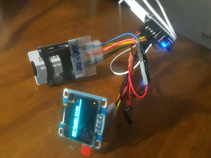
SD 카드 연결

작동사진

참조 사이트
https://www.instructables.com/id/SD-Card-Module-With-ESP8266/
SD Card Module With ESP8266
SD Card Module With ESP8266: In this assembly, we have an SD Card connected to the ESP8266. We put a DHT22, which measures temperature and humidity and sends this information to the SD card.On the circuit, it shows humidity of 43.40 and a temperature of 26
www.instructables.com
https://github.com/G6EJD/ESP8266-SD-Card-Reading-Writing/blob/master/ESP8266_D1_MicroSD_Test.ino
G6EJD/ESP8266-SD-Card-Reading-Writing
Examples of using the SD-Card with the ESP8266. Contribute to G6EJD/ESP8266-SD-Card-Reading-Writing development by creating an account on GitHub.
github.com
'IoT_ESP8266' 카테고리의 다른 글
| ESP8266 Modbus - qModMaster (0) | 2022.07.02 |
|---|---|
| ESP8266 AD8232 - ECG 로거 제작 (0) | 2020.02.23 |
| ESp-01 : 두개의 다이얼 제어 (0) | 2019.01.16 |
| ESP-01 : 서버와 데이터 주고 받기 정리 (0) | 2019.01.14 |
| jQuery 사용하기 (0) | 2019.01.13 |

DIYworld